It’s just about become time where I move onto actually replacing the IPMI controller firmware. Up until now, I’ve been pretty worried about attempting it. Since there’s no in circut programming, a failed flash would involve removing the chip to reprogram it. I managed to track down something I could solder in place of it to make this process easier. It’s called a SOIC Emulator, and it’s surprisngly expensive (given it’s a couple bits of metal and plastic). I bought the ‘PA-DSO-1603-D420-16/2’ product, since it should fit in place of the existing flash chip (a MX25L12845EMI-10G).
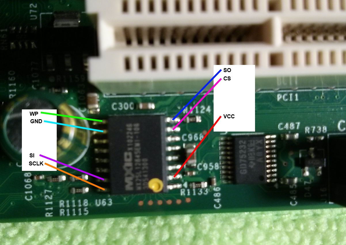
Step one ws taking a bunch of pictures of the board. Hopefully these are all the reference I need, since it’s pretty difficult to find high res pictures of these boards. Meet the IPMI flash memory chip. Without this, your IPMI controller is useless (in case you wanted to physically disable it):

I also labeled the pinout. This isn’t terribly helpful though, the board is designed in such a way that you can’t program it without removing it. Flashrom does detect this, so that’s a start.
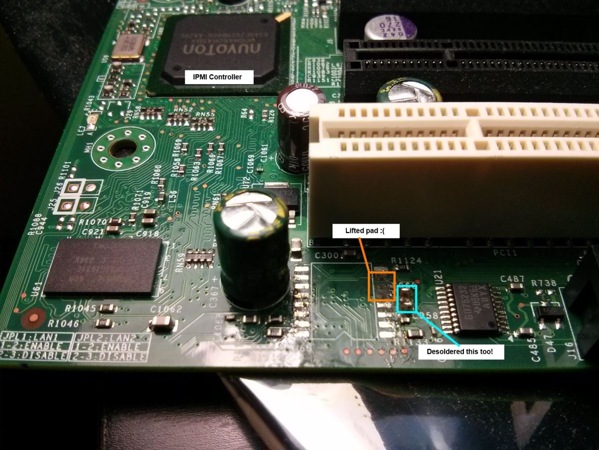
Step two is the scary one. You have to desolder a surface mount chip that has very little clearance. I don’t do a whole lot of soldering (and no SMT soldering), so I don’t have any of the tools that would make this process easy. Instead, I tried to do it with a Sparkfun soldering iron, some desoldering wick, and a razor blade.
This worked okay, but I ended up lifting a couple solder pads. Luckily, these weren’t terribly important. Two of them aren’t used here (they’re for parallel data in/out, but this is used in serial mode). The third is chip select; but there’s only one chip so I can just connect it to VCC/GND (I forget which right now).
It’s not pretty, but it did the job (hopefully!). Now I just need to wait until I get the replacement parts.
